|
|
|
| Reference Series |
Table of Contents For This Issue
|
|
| |
| How Computers Work, Part I | |
|
August 2001• Vol.5 Issue 3 Page(s) 30-35 in print issue | |
Unveiling The Mysterious Motherboard A Behind-The-Scenes Look At One Of Your PC's Most Vital Components |
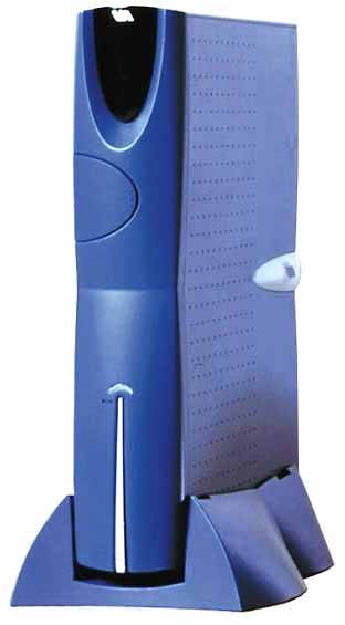
 Although motherboards come in several shapes and sizes, they all contain the computer’s essential interconnection circuitry, which is frequently imprinted on the board’s top and bottom. Other motherboard adornments include sensitive resistors, capacitors,
and electronic components, plus soldered connectors, slots, and sockets. In a desktop computer, the motherboard rests on the bottom of the case. In a tower or mini-tower configuration, the motherboard lines one of the sides.
Although motherboards come in several shapes and sizes, they all contain the computer’s essential interconnection circuitry, which is frequently imprinted on the board’s top and bottom. Other motherboard adornments include sensitive resistors, capacitors,
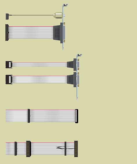
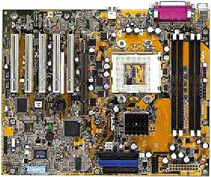
and electronic components, plus soldered connectors, slots, and sockets. In a desktop computer, the motherboard rests on the bottom of the case. In a tower or mini-tower configuration, the motherboard lines one of the sides.Motherboard features and component arrangements vary from one model to another. But a motherboard is at the core of every computer system. It defines a PC’s potential. Anything you want to add to your computer connects to it via the motherboard, and virtually every important computer component, data bus, or electrical subsystem also attaches to it in some way. If the motherboard fails, the computer will not function. There are several things you should look for when purchasing motherboards. Some of the most important motherboard characteristics include processor type (Intel Pentium III or 4, Intel Celeron, or AMD Athlon, for example), processor speed (measured in megahertz; 1.7GHz, for example), and processor cache (measured in kilobytes; 256KB, for example). Characteristics, such as the maximum amount of memory the board supports, the system bus, the number of memory slots onboard, whether the board has integrated audio or modem circuitry, and the range of speeds supported by the processor, may not be distinguishable when shopping for a motherboard. It’s these features, however, that determine your motherboard’s upgrade path. Not every motherboard can support the same options. You will run into problems if you try to add an AGP(Accelerated Graphics Port) card to a PCI(Peripheral Component Interconnect) motherboard, for example, because the AGP card will not fit. AGP is a high-performance, component-level technology for 3-D graphical display. An AGP slot on the motherboard is dedicated to 3-D-savvy graphics adapters that run two (2x) to four(4x) times the speed of the PCI bus. You want to be aware of certain factors before you swap one CPU for another. Certain processors function correctly only when installed on particular motherboards. Users who want to upgrade a Slot 1 Intel Pentium III processor to a newer Socket 423-based Pentium 4 processor won’t meet with success. You can’t just pop it in the CPU socket. For the upgrade to work, the motherboard must be equipped with a Slot 423 socket and an ATX12V power connector.As if that wasn’t enough, the heat sink retention mechanism requires four extra mounting holes. That means a new case must be purchased, too. Some manufactures, such as ASUS (with their P4T motherboard), include a metal baseboard to save users from purchasing another case. CPU(central processing unit). Also known as the microprocessor, this chip contains the computer’s central processing and control circuitry. All computer components channel data and instructions to and from the CPU. In newer PCs, the CPU is typically an Intel Pentium III, Pentium 4, or Celeron, or AMD Athlon. RAM(random-access memory.) This is slots or sockets and integrated circuits or chips surface-mounted on small circuit boards. The more RAM you can install in a computer (up to the maximum supported by the system), the better. RAM enables a computer to store actively running applications and their data without swapping out to the hard disk drive. Cache socket. This socket is reserved for a Level 2 cache (L2, cache memory that can be accessed more quickly than the primary cache) or secondary cache memory module. L2 cache consists of fast memory called SRAM (static RAM ). Computers with L2 cache perform better than those that lack L2 cache. This cache stores operations or data recently accessed by the CPU, allowing the processor to retrieve this information much more quickly than if the data resided in conventional RAM. System chipset. Also called the "support chipset," this collection of logic circuits is responsible for transferring information to and from all other motherboard circuits, adapter card connectors, and disk drives. Chipset specifications allow for compatibility with PCI and ISA(Industry Standard Architecture) buses and the IDE(Integrated Drive Electronics) disk storage interface. Motherboards may or may not be compatible with particular chipsets. For example, several years ago Intel Pentium III motherboards did not support the company’s own 810 chipset (which reduced system costs because of integrated graphics capabilities), even though Pentium III motherboards were developed initially with the 810 chipset in mind. A silicon fix for the problem was incorporated into Intel’s 810e chipset in late 1999. Expansion bus slots. Typically include PCI, ISA, and AGP connectors for adapter cards designed to handle audio, video, and other subsystems. Once added, adapter cards fasten to the back of the case with a screw. Without slots, a computer would be limited to the circuitry permanently wired to the motherboard. Disk interface. Connectors for floppy diskette and IDE hard disk drives. You attach a ribbon cable from a disk interface connector on the motherboard to the hard drive or floppy drive that resides in a bay on the chassis. Miscellaneous I/O (input/output) ports and connectors. These devices get their name because information is sent in and out of them. One example is on older motherboards, where you attach a cable from a parallel port connector on the motherboard to a LPT(line printer terminal) port on the back panel of the computer chassis, which then connects to a printer. You can also attach cables from serial port connectors on the motherboard to ports on the back panel of the chassis to connect serial modems and scanners. Newer computers eliminate the need for cables because the connectors are integrated on the board. Newer motherboards also have hardwired USB (Universal Serial Bus) connectors letting you attach USB devices to the computer’s back panel. A mouse connector on the motherboard cables to a PS/2-style port at the back of the computer for input devices such as a mouse or trackball. A keyboard connector (typically hardwired to the motherboard) cables to a keyboard port at the panel at the back of the computer so you can attach a keyboard. System BIOS. The BIOS(Basic Input/Output System) chip holds the code that starts up your computer. Newer systems have a flash BIOS, storing the code on EPROM(erasable programmable read-only memory), memory that can be erased when exposed to ultraviolet light), so users can easily update a system’s existing BIOS with new code. Miscellaneous parts. This category includes the CMOS(complementary metal-oxide semiconductor, an electronic component used for RAM and fast data switching), real-time clock (the battery-powered device that keeps track of system time and date), plus several configuration jumpers and switches, power connectors, light-emitting diodes, and front-panel electrical connectors. As the motherboard works, data and timing signals transfer from one connected component to the other by way of interconnected leads etched into the board. These leads are known as the system bus. The power supply, which also connects to the motherboard, distributes power to all system components via the bus. The processor also communicates with motherboard components by sending and receiving instructions and data over the bus. When all goes well, information travels through these various motherboard components on its way to its final destination, whether that destination is the monitor, hard drive, or other device. Say, for example, you press a key on your keyboard. That information signal passes from your keyboard’s own microprocessor through the keyboard’s cable that connects to the back of your PC. The signal then moves to the computer’s processor, which processes the request. If there are other signals waiting to be processed, they are held in the RAM buffer. The processor then translates signals into information your monitor can interpret. The signal moves to the graphics adapter, and from there it displays on-screen. While that’s the path information takes from your keyboard to your monitor, the process works basically the same no matter what you’re doing; only the recipient of the input changes. One final way that motherboards differ is the method by which the installed CPU connects to the board. Pentium processors in Slot 1 configuration motherboards, such as boards that support Intel’s Pentium II Celeron, attach to the motherboard through a 242-contact slot connector. Higher-end Pentium II Xeon processors use a Slot 2 configuration, which means that the CPU sits in a 330-contact slot connector. PGA (pin grid array) 423 Intel Pentium 4 (1.4GHz to 1.7GHz at press time) CPUs require a Socket 423 and are moving away from the slot option. Older Pentium processors connect to the motherboard through a ZIF (Zero Insertion Force) socket. There were eight motherboard configurations of this type. They differ in the number of pins on the socket, whether the socket uses standard or staggered pin grid array technology (if pins are staggered, more of them sit closer together on the chip), and the voltage or power the chip consumes. The best-known ZIF socket configuration is the one identified as a Socket 7 (321 pins, staggered layout, 3 volts). In 1997, when Intel introduced the Pentium II processor, it moved from the ZIF (Socket 7) motherboard configuration to a slot connector approach. Intel later introduced a low-cost socketed version of its 550MHz and 600MHz Pentium III CPUs because socketed chips allow manufacturers to produce thinner PCs. Early AT-style motherboards were designed to slip into full-sized desktop systems. Mini AT (8.7 x 13 inches) and Baby AT (8.57 x 13.04 inches) variations followed. They had smaller form factors made possible by component miniaturization. By integrating the circuitry for particular peripheral components onto the board, these form factors required less physical space. Their smaller size permitted the design of mini-tower and minidesktop systems. Then came the new improved ATX(Advanced Technology Extended-style) motherboard, created by Intel in 1995. This form factor was engineered to simplify and standardize the ways in which clone manufacturers produced motherboard designs. ATX boards had a maximum size of 12 x 9.6 inches, and they looked like a Baby AT board rotated 90 degrees. The ATX form factor had the same width as a full-sized AT board, but it had special design considerations to accommodate the newer and larger Pentium Pro and Pentium II processors. The original specification for the LPX(Low Profile Extended) motherboard was developed by Western Digital in 1986 for internal corporate use. However, the company’s innovative low-profile form factor quickly garnered outside attention. LPX motherboards were designed to reduce space and cost, and they soon figured prominently in the smaller slim-line "pizza box" style desktop cases, which were meant to fit underneath a typical monitor. Instead of having expansion card slots built into the motherboard, slots were set on a riser card that plugged into the motherboard’s single slot connector. Adapter cards, which inserted into the riser card’s slots (set on either one or both sides of the card), lay parallel to the motherboard, thus reducing the overall height of the system chassis. But the LPX design wasn’t perfect. Only some riser cards allowed for full-length I/O cards. In addition, installing I/O cards parallel to the motherboard generated clutter while creating several temperature pockets that prevented good airflow through the system. Also, users had to remove I/O cards from the riser to gain access to components installed on the board.
The ATX form factor added several improvements to the AT models from which it evolved. It also reduced overall system cost. For example, Baby AT designs required that parallel and serial connectors on the motherboard be cabled to connectors on the back panel of the chassis. By integrating these I/O connectors on the motherboard, an ATX form factor eliminated the parallel and serial cables, reducing system cost and clutter. Taking out the cables also cut down EMI(electromagnetic interference) emissions, because cables often act as antennas picking up or radiating unwanted interference. The ATX form factor also included a power supply with an optimized side-mounted fan. The new fan design provided protection against overheating, while reducing system cost by making a secondary fan or active heat sink unnecessary in most system applications. Instead of blowing air out of the chassis, as with most Baby AT platforms, the power supply fan drew air through the chassis and across the CPU. In addition, the longer side of the board could be used to host more onboard I/O, thus reducing the number of cables and system components. By positioning the processor away from the expansion slots, all slots could now hold full-length cards. Other ATX changes improved the position of hard and diskette drive connectors by placing them closer to the peripheral bays to allow for the use of shorter cables. SIMM connectors were moved farther away from the expansion bays and slots, making it easier for users to install memory upgrades. The ATX 2.03 specification requires four mouting holes around the Socket 423 connector for the heatsink mechanism and an ATX12V power supply for Intel’s i850 chipset to be properly powered. These requirements are for the Intel Pentium 4 In November 1996, designs emerged for the low-profile NLX motherboard. The board was designed by Intel, IBM, and other key PC manufacturers worldwide, and it was engineered to resolve accessibility, serviceability, and temperature issues inherent in the LPX specification. The board, which was released in March 1997, featured support for the latest processor technology (at the time it was the Pentium II), and it allowed improved access to upgradeable components in low-profile design systems by providing a dockable motherboard for easy installation and removal. The add-in riser card in an NLX now inserted at the right edge of the motherboard (when viewed from the front) rather than somewhere near the middle. The processor and RAM slots were in the front left section of the board to improve cooling, optimize clearance issues, and allow the I/O slots on the riser card to hold full-length add-in cards. I/O connectors at the back of the motherboard were stacked single and double high to support additional connectors. In addition, the NLX also supported AGP graphics. Systems based on the space-saving micro ATX specification appeared in the first half of 1998, although Intel announced this new form factor in December 1997. The micro ATX was not intended as an ATX form factor replacement but rather as a less expensive alternative. A micro ATX motherboard measures 9.6 x 9.6 inches and can reside in a larger ATX or smaller micro ATX chassis. However, the simplified construction and smaller design of a micro ATX motherboard permits a reduced-sized power supply and chassis. A micro ATX system can have up to four expansion slots for add-in cards. By offering support for fewer I/O slots and peripheral bays, a micro ATX form factor reduces the overall cost of system design. The design of the micro ATX form factor is so versatile that vendors can integrate audio and AGP solutions on the motherboard, enabling users to reserve the expansion slots for other functions. VIATechnologies (http://www.viatech.com.tw) announced its new ITX(Internet Technology Extension) form factor at CeBIT2001 in Hannover, Germany in spring 2001. The ITX standard integrates support for USB, IEEE 1394 (FireWire), and TV Out, along with an ACR (Advanced Communication Riser) slot for software fax/modem and 10/100Mbps Ethernet. The Socket 370 CPUsupport is built for VIA Cyrix III processors. Via hopes to see $200 to $500 systems built around this form factor. When it comes to notebook motherboards, there are no standard form factors. A typical notebook computer doesn’t have just one main board. Rather, it houses a collection of small boards distributed in different locations around the notebook. If you pop the lid or flip up the keyboard on a typical notebook computer, you would see only one of the computer’s many boards. The particular boards installed differ from model to model. Even within model "families," there are variations. For example, let’s use an IBMThinkPad:each ThinkPad is designed around a different motherboard configuration.
But according to Mihacsi, form factors aren’t what drive PC purchases. People are more interested in stylish-looking PCs that are easier to use, less expensive, and equipped with the latest technologies, he says. Although it’s difficult to predict what the next desktop PC motherboard form factor will look like, the trend is toward smaller footprints and tighter component integration. The goal is to reduce system costs while improving ease of use, he says. "It’s a balancing act," explains Mihacsi. "Both the consumer and corporate models have changed over time as has the technology," he says. Mihacsi says style must always be considered along with standards, because costs are higher for custom board designs. The challenge is to build a PC based on a standard form factor, yet offer the latest technology, while addressing as many market or customer needs as possible. Intel tried to put this goal into practice with the announcement of the FlexATX, which calls for cutting motherboard size by as much as 25% from the micro ATX standard. Boards measure 9 x 7.5 inches. This smaller size will allow a FlexATX to fit into a smaller chassis that takes up less space on the user’s desk. The FlexATX is optimized for low-cost, space-constrained applications, and it derives its name from its inherent system design flexibility. Motherboards conforming to the Flex specification are small enough to be enclosed in all-in-one computing devices, LCD personal computers, and standard desktop systems. Because a FlexATX sports the same motherboard mounting holes as the micro ATX form factor, it can fit in either an ATX- or micro ATX-compliant chassis. "FlexATX encourages a lot more differentiation," Mihacsi says. "It is based on the model that says that users don’t want or need a lot of I/O expandability, watts, and slots for added peripherals." Here the design paradigm is one that’s more in tune with ease of use than style. Because FlexATX has the ability to access different types of peripherals, and it supports processor and memory upgrades, Mihacsi believes its high degree of component integration represents a significant cost savings to end users. Value-added resellers, on the other hand, can think of a few reasons why the trend toward component integration may not be the best for all consumers. They suggest that integrating subsystems such as sound, video, and networking on the motherboard reduces system flexibility. When standards change and users try to add an I/O card to take advantage of new features, problems often result. Diagnosing the cause of a conflict that may result when adding adapter cards to a motherboard already top-heavy with integrated components is not only difficult, but it is often impossible to resolve. by Carol S. Holzberg, Ph.D. View the graphics that accompany this article. (NOTE: These pages are PDF (Portable Document Format) files. You will need Adobe Acrobat Reader to view these pages. Download Adobe Acrobat Reader) View the chart that accompanies this article. (NOTE: These pages are PDF (Portable Document Format) files. You will need Adobe Acrobat Reader to view these pages. Download Adobe Acrobat Reader)
|