
|
|
|
| Reference Series |
Table of Contents For This Issue |
|
| |
| How Computers Work, Part I | |
|
August 2001• Vol.5 Issue 3 Page(s) 36-41 in print issue | |
Where Peripherals Come Into Port Interfaces From Serial To FireWire Keep PCs In Touch With Components |
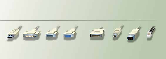 A personal computer is little more than an expensive doorstop without the ports and interfaces that connect the numerous devices and peripherals to the PC. Without these connections inside and outside the PC, devices can’t send or receive information, which
means the CD-ROMs won’t play, the mouse won’t control anything on-screen, and everything on the hard drive is there to stay. That means these PC connections have a role much bigger than the amount of attention they get.
A personal computer is little more than an expensive doorstop without the ports and interfaces that connect the numerous devices and peripherals to the PC. Without these connections inside and outside the PC, devices can’t send or receive information, which
means the CD-ROMs won’t play, the mouse won’t control anything on-screen, and everything on the hard drive is there to stay. That means these PC connections have a role much bigger than the amount of attention they get.Today’s systems make your interaction with ports and interfaces mostly hassle-free. Modern PCs usually ship with brightly colored labels signifying what peripheral plugs in where, and the connecting cable is usually color-coded to that label. This makes setting up a new PC a snap. You simply plug the orange end of the printer cable into the port marked with the orange picture of a printer, for example, without even considering port technology. Sometimes, however, you’re forced to dig more deeply into the technical details of your computer’s connections. With so many internal and external ports available, it’s easy to get confused about what peripheral goes where and how it communicates with the PC. If discussions of parallel ports, serial ports, and SCSI interfaces sound like a foreign language to you, this article will help. It clarifies the significance of these terms and summarizes how they’re pertinent to your PC. A typical consumer PC usually includes two serial ports, one parallel port, two to four USB ports, two PS/2 ports, one AGP slot, one ISA slot, an IDE or EIDE interface, and two to four PCI slots. On a high-end or multimedia PC, you’ll also find two IEEE 1394 ports and probably a SCSI interface. Keep reading to find out the details of what’s going on behind all this alphabet soup. External PortsThe electrical interface used to connect the serial port to the device is the RS-232 (Recommended Standard 232) or the newer RS-422 and the similar RS-485. These interfaces are backward compatible, which means you can use an RS-422-capable device with an RS-232 interface. The RS-232 has a few downfalls, including a maximum transmission rate of 20Kbps (kilobits per second) and the restriction that a device must be located within 50 feet of the system. The RS-422 supports transmissions rates above 20Kbps and longer cables and offers greater immunity to interference that sometimes occurs with an RS-232. The parallel port is the largest port on the rear of your PC, comprising 25 lines that include 17 signal lines and eight ground lines. The signal lines are divided into Control, Status, and Data groups. The Control lines serve as an interface between the PC and printer, sending information such as initial handshaking signals when both units are turned on. Status lines keep track of any errors, such as messages that the printer can’t print a certain font, the paper tray is empty, or the printer is busy. (Status lines were introduced with the bi-directional parallel port in the 1990s.) The Data lines deliver commands from the PC to the printer to print a document. Epson initially designed the parallel port to feature a maximum data transfer rate of 150Kbps in a technology now known as the Centronics standard. Two successive standards, the EPP (Enhanced Parallel Port) and ECP (Extended Capabilities Port), have increased this data transfer to more than 1MBps (megabyte per second). The EPP and ECP, also known as the IEEE (Institute of Electrical and Electronic Engineers) 1284 standard, are compatible with the standard parallel port and support bi-directional communication, unlike the older Centronics technology. Bi-directional signaling means the device can communicate interactively with the PC. The ECP can adapt to the device, the PC, and the various cable lengths that may connect the two. This means the ECP’s data transfer rate can vary from 2MBps to 4MBps. The EPP is best used for attaching devices such as tape drives or adapters. Because one SCSI port can support up to eight devices at once, it’s often referred to as an I/O (Input/Output) bus. (A port can support up to two devices, but a bus is intended for connecting numerous devices to the PC. We will refer to the SCSI interface as a port.) An I/O bus assigns an identifying number to each connected device. A SCSI interface can host a maximum of eight devices, which includes the SCSI “host” adapter. When the SCSI port communicates with the device, it recognizes the device ID and proceeds to transfer the appropriate data. SCSI’s capabilities for accommodating so many devices make it a good fit for networked computers or servers that must accommodate multiple hard drives and peripherals. Most consumer systems don’t have these requirements, so the majority ship with IDE interfaces rather than SCSI. SCSI port operation begins when the port initiates a handshake with the device to establish its presence and then initializes contact with it when the device sends its ID number to the port. If multiple devices simultaneously send a command, devices with the higher ID numbers receive priority. Once the device completes a commanded operation, such as printing a page or initializing a DVD-ROM program, the port resets itself to accept commands again. SCSI technology has advanced since its origin in 1986. SCSI-1 started out with an 8-bit bus and a 5MBps transfer rate, and SCSI-2 followed with a 20MBps transfer rate. SCSI-3, also referred to as Ultra Wide SCSI, appeared in 1996 with a 16-bit bus and a data transfer rate of 40MBps. SCSI-3 introduced support for fiber-optic cable. One variety of SCSI-3 technology is Wide Ultra2 SCSI, which features a 16-bit bus and a data transfer rate of 80MBps. SCSI’s downfall is its many varieties and lack of a single standard, which means some devices may not work with certain SCSI boards. If you can find a SCSI device that works with the SCSI port on your PC (or comes with its own SCSI card), however, this interface is an attractive option because of its high data transfer rate. Even though you can attach multiple devices to the PC through USB, only one must be plugged into the USB port. Other peripherals are added through USB hubs, which might be integrated into the peripheral connected to the PC or packaged as a separate USB hub, which costs about $40. When you plug a device into a USB port, the system searches for and loads the required device driver, then checks periodically to see whether the peripheral is connected. If you detach the peripheral but reattach it later, the system recognizes it without reinstalling a driver. The latest development in USBtechnology is USB 2.0, which has been called Hi-Speed USB becuase it has a bus speed of 480Mbps, which is 40 times faster than USB 1.1. This latest version of USBis expected to be available to consumers in the fall of 2001. Best of all, USB 2.0 is backward compatible with the original USB systems and peripherals. FireWire-capable PCs usually feature two ports shaped like rectangles with a slightly curved end and a connector on the inside. Like USB, FireWire supports Plug and Play and hot plugging and has a quick data transfer rate of 400Mbps to 800Mbps. FireWire works similarly to the IDE interface in that each device connected is assigned an address, and devices with a higher address have top priority as commands flow into the system. As FireWire products continue to decrease in price, the competition with USBcontinues to increase. One thing fanning the flames of this rivalry is the impending release of the Windows XP OS (operating system). Initial reports stated that Microsoft was not going to include USBsupport in at least the initial release of WinXP, choosing instead to offer compatibility withFireWire. Soon after, however, Microsoft asserted that it will try to include some type of support for USB 2.0 as well, either in the newest version of WinXP or a later release. One of the issues affecting this decision is that USB 2.0 products are still widely unavailable. Storage InterfacesIDE transfers data more slowly than the SCSI interface, but it’s more commonly used because it’s less expensive and requires no additional expansion card. IDE is usually intended specifically for use with hard drives and CD-ROM drives, whereas SCSI and EIDE are intended for various hardware devices. The IDE interface cable connects two devices at a time, such as the hard drive and the CD-ROM drive, to the IDE interface on the motherboard. The interface can support up to four devices if you opt to add something such as an internal Zip drive or CD-RW drive. IDE is sometimes referred to as ATA (Advanced Technology Attachment). Each IDE device connects to the motherboard with an IDE cable, which features two female connectors that attach devices such as a hard drive or CD-ROM drive. Because IDE interfaces on the motherboard are limited, using the cable with two connectors allows more than one IDE device to be connected at a time. This cable should be fairly short (less than 18 inches) to prevent interference. Before IDE, the ST-506/ST-412 interface connected the first hard drives to PCs. This interface used two cables, with a 20-pin cable carrying data and a 34-pin cable carrying control signals. The ST-506/ST-412 setup was slow and prone to error. As a solution, engineers created the ESDI (Enhanced Small Device Interface) in the 1980s. The ESDI had increased data throughput, but it was short-lived because of the introduction of IDE, which offered quicker performance at a lower cost. Each of these previous interfaces placed the drive controllers on an interface card in the PC. The IDE interface integrates the logic board on the hard drive, which means the information goes directly to the motherboard rather than relying on an expansion card. Current IDE interfaces feature data transfer rates from 16.7MBps to 33MBps and use a 40-pin connector. The IDE interface communicates between the device and PC via channels, with each channel requiring an IRQ (interrupt request line) and two I/O addresses. An IRQ is a communication tool assigned to each device that sends interrupt signals through hardware lines to the microprocessor. Commands coming from a device assigned a higher priority get the most immediate service from the processor. The EIDE port is located beside the IDE port on the motherboard and features a 40-pin connector. With the introduction of Ultra DMA (or ATA-33) in 1997, transfer rates rose to 33MBps, and in 1999, Ultra DMA (ATA-66) arrived with rates of 66MBps. ATA-66 uses a different cable from typical IDE, featuring 80 conductors (40 for grounding and increasing transfer capability, plus the regular 40-pin connector). Internal Ports/SlotsThe AGP port communicates directly with the PC’s main memory rather than sending data through a PCI bus. This leaves plenty of bandwidth (data transmission capability) for devices connected to a PCI slot and provides rapid communication between the video card installed in the AGP port and the PC. As graphic textures are needed, the AGP port sends the request directly to the system memory for execution. The brown AGP port is located near, and is about the same size as, the motherboard’s white PCI slots. It’s easy to differentiate these slots from the other free slots on the motherboard: the black Industry Standard Architecture slots. In 1999, AGP4X came on the scene, bringing data transfer rates of 1,024MBps and clock speeds of 66MHz. 1999 also brought the release of the AGP Pro slot, which is fully backward compatible with AGP. The 16-bit ISA bus standard has changed little since its invention in the early 1980s. The slots accept either 8-bit or 16-bit cards, with the 8-bit cards using only the first half of the roughly 5.5-inch long slot. You’ll find fewer ISA slots than PCI slots in today’s systems simply because manufacturers make more expansion cards for the 32-bit PCI bus, which moves data more quickly and delivers higher performance. An 8-bit ISA slot has a bandwidth of 7.9MB per second, and a 16-bit ISA slot runs at 15.9MB per second. PCI has a bus bandwidth of 127MB per second at 32 bits and 508MB on 64-bit PCI slots. The PCI slot sends requests for service from the card to the processor in the form of interrupts, which are assigned to a normal IRQ. PCI improves performance by letting two devices share an IRQ. PCI slots have soared in popularity because of their high-performance capabilities and Plug-and-Play qualities. Plug and Play lets you plug in a device and begin using it immediately without messing with any configurations. The slot supports both 32-bit and 64-bit cards, but PCI has failed to eliminate the need for the ISA bus, as many observers predicted. Nearly every system still includes at least one ISA slot to accommodate older expansion cards. by Buffy Cranford-Petelle View the graphics that accompany this article. (NOTE: These pages are PDF (Portable Document Format) files. You will need Adobe Acrobat Reader to view these pages. Download Adobe Acrobat Reader) View additional graphics that accompany this article. (NOTE: These pages are PDF (Portable Document Format) files. You will need Adobe Acrobat Reader to view these pages. Download Adobe Acrobat Reader) View additional graphics that accompany this article. (NOTE: These pages are PDF (Portable Document Format) files. You will need Adobe Acrobat Reader to view these pages. Download Adobe Acrobat Reader)
|